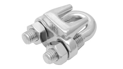
S260 4MM 316 Wire Rope Grip

S260 4MM 316 Wire Rope Grip

S260 4MM 316 Wire Rope Grip

S260 4MM 316 Wire Rope Grip
MFWG604
In Stock
BPIR (click to view)
Your cart has been updated.

S260 4MM 316 Wire Rope Grip

MFWG604
In Stock
BPIR (click to view)
Stainless Steel S260 Wire Rope Grip
Your cart has been updated.
In Stock
BPIR (click to view)

Anzor Building
Product Information Sheet

{this.state.description}

Product Disclosure Information Self-Assessment
Version:
Product name-
Product line-
Product identifier-
Product description.
-
Relevant building code clauses
-
Contributions to compliance
-
Scope of use
-
Conditions of use
Items should be used as specified by a qualified engineer.
Contact details
Manufacture location-
Legal and trading name of manufacturer-
Legal and trading name of importerAnzor Fasteners Ltd
Importer address for service93 Apollo Drive, Rosedale
Auckland 0632
Importer websitewww.anzor.co.nz
Importer NZBN9429038848490
Importer emailsales@anzor.co.nz
Importer phone number09 476 0001
Warnings and bans
Is the building product/building product line subject to warning or ban under section 26 of the Building Act 2004?
No

Appendix
BPIR Selections
-
Building code performance clauses
All relevant building code performance clauses listed in this document:
-
Installation

Anzor 316 Wire Rope Grip Installation Instructions

1. Equipment & Tooling Standards

For best results and trade-standard practice, all tools and equipment:

  • Must be well-maintained, serviced, not worn out, and easily capable of performing the task.
  • Should be dedicated to and used for Stainless Steel exclusively to prevent carbon contamination and tea-staining.
  • Crescents, sockets, and drive bits should ideally be Chrome Vanadium steel.
  • Allen keys must be Hardened-Chrome plated.
  • Cutting wheels must be Aluminium Oxide and explicitly certified iron-free / carbon-steel free.
  • Hammers must be high-quality hardened-chrome plated steel or solid stainless steel.

https://www.anzor.co.nz/technical/stainless-steel-overview/the-dos-and-donts-of-stainless-steel-fasteners

2. Pre-Assembly Visual Inspection

Visually inspect all assemblies and wire rope lines before beginning:

  • Check for any signs of premature corrosion, staining, sizing mismatches, manufacturing defects, kinks, or broken/damaged strands.
  • Verify labelled components match the required material grade and dimensions specified in the engineering schedule.
  • Confirm all threaded components can be easily spun by hand before loading.


3. Preparation & Cutting Sequence

  1. Record Batch Numbers: Track and log batch numbers (must be explicitly requested from Anzor at point of sale).
  2. Map Layout: Measure and map out the wire rope assembly point-to-point. Factor in: Number of Wire Rope Grips required (Refer to Table 1 on Specifications). Minimum Turnback Lengths (Refer to Table 1 on Specifications). Loops, crimps, internal swage cavities, tensioning slack, and take-up margins. Inherent wire stretch (especially critical on long runs and 7x7 or 7x19 wire configurations).
  3. Dry Fit: Dry fit the complete assembly with all tensioning components fully unwound. Re-confirm point-to-point layout, mark cutting locations with a vivid marker, and label distinct lines using white tape.
  4. Execute Cut: Cut the wire rope cleanly. Temporarily wrap insulation tape tightly around exposed cut ends to prevent unlaying.
  5. Pre-Install Hardware: Slide on any Wire Standoffs, Eyes, or secondary components that cannot be installed after terminals are crimped or gripped.


4. Lubrication & Terminal Assembly

  1. Terminal Lubrication: Lubricate the internal threads of any Swage or Crimp turnbuckle components with Prolan, Tef-Gel, Chemz, CRC, or Loctite Nickel Anti-Seize. 
  2. Swage Terminals: Execute swages on swage components according to the attached Swage Tool Instruction Manual.
  3. Crimp Terminals: Crimp copper/alloy sleeves using the calibrated tool specified for the wire diameter.
  4. Grip Thread Lubrication: Lubricate the threads of all Wire Rope Grips with Prolan, Tef-Gel, or Nickel Anti-Seize before assembly to prevent severe thread galling under high-torque loads. 


5. Wire Rope Grip Clamping Sequence

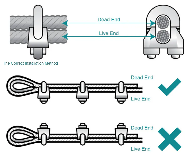
  1. Grip #1 (Loop/Thimble End): If using a thimble loop, place the first grip immediately adjacent to the thimble collar, ensuring the thimble points do not slice into the wire strands. Orientation: The U-bolt must wrap over the dead tail line; the saddle must cup the live load line. Tighten nuts to 50% of the target torque value (Refer to Table 1 on Specifications).
  2. Grip #2 (Tail End Placement): Pull the dead-end tail line completely taut to eliminate slack inside the turnback. Secure the second grip exactly one bridge-width away from the dead-end tail of the wire rope. Ensure matching U-bolt orientation (saddle on live line). Tighten nuts to 50% of the target torque value (Refer to Table 1 on Specifications).
  3. Grip #3+ (Intermediate Placement): Place all remaining intermediate grips evenly spaced between Grip 1 and Grip 2, adhering strictly to the Minimum Grip Spacing values (Refer to Table 1 on Specifications).
  4. Final Torquing Sequence: Working sequentially from the thimble outwards toward the tail, torque all nuts progressively up to 100% of the target Nm specification using a calibrated digital or click torque wrench.


6. Commissioning & Final Sign-Off

  1. Pre-Load Inspection: Inspect all finished components, terminations, and clearances. Confirm swages, crimps, and grip layouts are uniform and fully seated.
  2. Initial Tensioning: Tension the system slowly. Closely monitor all swages, crimps, and grips for signs of slippage or rope deformation.
  3. MANDATORY RE-TORQUE: After applying the initial tension or proof load, immediately re-torque all grip hex nuts to the full target Nm value to compensate for initial rope diameter compression.
  4. Compliance Logging: Tag, label, and log the completed assembly data as required by the site quality assurance program.

Legal Disclaimer

Important Notice: Read Before Proceeding with Installation

The installation instructions and technical data provided herein are for general informational and illustrative reference purposes only. Wire rope termination involves inherent risks to property, structural integrity, and personal safety.

By utilizing this document, you acknowledge and agree to the following terms:
  • No Professional Liability: The author, publisher, and associated technical resources (including Anzor Fasteners) disclaim all liability for any direct, indirect, incidental, or consequential damages, injuries, or structural failures resulting from the use, misuse, or misinterpretation of these instructions.
  • Engineering Precedence: This document does not replace site-specific engineering schedules, certified rigging designs, or regulatory maritime/construction standards. You must defer to qualified professionals and certified engineers for project-specific calculations.
  • Compliance with Standards: All installations must comply with local statutory regulations, workplace health and safety laws, and relevant national standards governing wire rope rigging and architectural installations.
  • Load Rating Restrictions: Wire rope grips must never be used to form a loop or termination for overhead lifting, hoisting, or personnel suspension unless explicitly certified for such use by an authorized safety engineer.
  • Required Inspections: Terminations are subject to material fatigue, rope stretch, and mechanical loosening. Regular inspection, maintenance, and adherence to the mandatory re-torque protocols outlined in Section 6 are the sole responsibility of the installer and asset owner.
Specifications

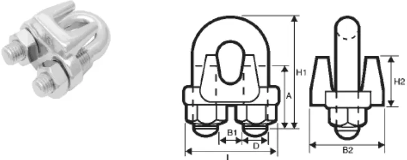
1vhofplgx Ujx0u8 Image1 Wiregrip

TABLE 1

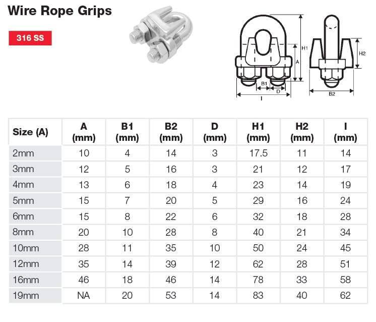
Product Code Matching Wire Rope (mm) A (mm) B1 (mm) B2 (mm) D (mm) H1 (mm) H2 (mm) I (mm) Thread Size Critical Rigging Target Torque Critical Rigging - Min. Grips Architectural Target Torque Architectural - Min. Grips Minimum Grip Spacing (mm) Minimum Turnback Length (mm)
MFWG602 2 10 4 14 3 17.5 11 14 M3 0.15 Nm 3 clips 0.10 Nm 2 clips 12 45
MFWG603 3 12 5 16 3 21 12 17 M3 0.15 Nm 3 clips 0.10 Nm 2 clips 18 65
MFWG604 4 13 6 18 4 23 14 19 M4 1.50 Nm 3 clips 1.00 Nm 2 clips 24 85
MFWG605 5 15 7 20 5 29 16 24 M5 4.00 Nm 3 clips 2.50 Nm 2 clips 30 120
MFWG606 6 15 8 22 6 32 18 28 M6 4.50 Nm 4 clips 3.50 Nm 3 clips 36 140
MFWG608 8 20 10 28 8 40 21 34 M8 6.10 Nm 4 clips 5.00 Nm 3 clips 48 170
MFWG610 10 28 11 35 10 50 24 45 M10 9.50 Nm 4 clips 7.50 Nm 3 clips 60 230
MFWG612 12 35 14 39 12 62 28 51 M12 20.3 Nm 4 clips 15.0 Nm 3 clips 72 260
MFWG616 16 46 18 46 14 78 33 58 M14 40.7 Nm 4 clips 30.0 Nm 3 clips 96 360
MFWG619 19 50 20 53 14 83 40 62 M14 61.0 Nm 5 clips 45.0 Nm 4 clips 114 460

Rogwnrmguubjz5ve Wiregrip2

S260 4MM 316 Wire Rope Grip

S260 4MM 316 Wire Rope Grip

S260 4MM 316 Wire Rope Grip
MFWG604
In Stock
BPIR (click to view)
Your cart has been updated.

S260 4MM 316 Wire Rope Grip

MFWG604
In Stock
BPIR (click to view)
Stainless Steel S260 Wire Rope Grip
Your cart has been updated.
In Stock
BPIR (click to view)

Anzor Building
Product Information Sheet

{this.state.description}

Product Disclosure Information Self-Assessment
Version:
Product name-
Product line-
Product identifier-
Product description.
-
Relevant building code clauses
-
Contributions to compliance
-
Scope of use
-
Conditions of use
Items should be used as specified by a qualified engineer.
Contact details
Manufacture location-
Legal and trading name of manufacturer-
Legal and trading name of importerAnzor Fasteners Ltd
Importer address for service93 Apollo Drive, Rosedale
Auckland 0632
Importer websitewww.anzor.co.nz
Importer NZBN9429038848490
Importer emailsales@anzor.co.nz
Importer phone number09 476 0001
Warnings and bans
Is the building product/building product line subject to warning or ban under section 26 of the Building Act 2004?
No

Appendix
BPIR Selections
-
Building code performance clauses
All relevant building code performance clauses listed in this document:
-
Installation

Anzor 316 Wire Rope Grip Installation Instructions

1. Equipment & Tooling Standards

For best results and trade-standard practice, all tools and equipment:

  • Must be well-maintained, serviced, not worn out, and easily capable of performing the task.
  • Should be dedicated to and used for Stainless Steel exclusively to prevent carbon contamination and tea-staining.
  • Crescents, sockets, and drive bits should ideally be Chrome Vanadium steel.
  • Allen keys must be Hardened-Chrome plated.
  • Cutting wheels must be Aluminium Oxide and explicitly certified iron-free / carbon-steel free.
  • Hammers must be high-quality hardened-chrome plated steel or solid stainless steel.

https://www.anzor.co.nz/technical/stainless-steel-overview/the-dos-and-donts-of-stainless-steel-fasteners

2. Pre-Assembly Visual Inspection

Visually inspect all assemblies and wire rope lines before beginning:

  • Check for any signs of premature corrosion, staining, sizing mismatches, manufacturing defects, kinks, or broken/damaged strands.
  • Verify labelled components match the required material grade and dimensions specified in the engineering schedule.
  • Confirm all threaded components can be easily spun by hand before loading.


3. Preparation & Cutting Sequence

  1. Record Batch Numbers: Track and log batch numbers (must be explicitly requested from Anzor at point of sale).
  2. Map Layout: Measure and map out the wire rope assembly point-to-point. Factor in: Number of Wire Rope Grips required (Refer to Table 1 on Specifications). Minimum Turnback Lengths (Refer to Table 1 on Specifications). Loops, crimps, internal swage cavities, tensioning slack, and take-up margins. Inherent wire stretch (especially critical on long runs and 7x7 or 7x19 wire configurations).
  3. Dry Fit: Dry fit the complete assembly with all tensioning components fully unwound. Re-confirm point-to-point layout, mark cutting locations with a vivid marker, and label distinct lines using white tape.
  4. Execute Cut: Cut the wire rope cleanly. Temporarily wrap insulation tape tightly around exposed cut ends to prevent unlaying.
  5. Pre-Install Hardware: Slide on any Wire Standoffs, Eyes, or secondary components that cannot be installed after terminals are crimped or gripped.


4. Lubrication & Terminal Assembly

  1. Terminal Lubrication: Lubricate the internal threads of any Swage or Crimp turnbuckle components with Prolan, Tef-Gel, Chemz, CRC, or Loctite Nickel Anti-Seize. 
  2. Swage Terminals: Execute swages on swage components according to the attached Swage Tool Instruction Manual.
  3. Crimp Terminals: Crimp copper/alloy sleeves using the calibrated tool specified for the wire diameter.
  4. Grip Thread Lubrication: Lubricate the threads of all Wire Rope Grips with Prolan, Tef-Gel, or Nickel Anti-Seize before assembly to prevent severe thread galling under high-torque loads. 


5. Wire Rope Grip Clamping Sequence

  1. Grip #1 (Loop/Thimble End): If using a thimble loop, place the first grip immediately adjacent to the thimble collar, ensuring the thimble points do not slice into the wire strands. Orientation: The U-bolt must wrap over the dead tail line; the saddle must cup the live load line. Tighten nuts to 50% of the target torque value (Refer to Table 1 on Specifications).
  2. Grip #2 (Tail End Placement): Pull the dead-end tail line completely taut to eliminate slack inside the turnback. Secure the second grip exactly one bridge-width away from the dead-end tail of the wire rope. Ensure matching U-bolt orientation (saddle on live line). Tighten nuts to 50% of the target torque value (Refer to Table 1 on Specifications).
  3. Grip #3+ (Intermediate Placement): Place all remaining intermediate grips evenly spaced between Grip 1 and Grip 2, adhering strictly to the Minimum Grip Spacing values (Refer to Table 1 on Specifications).
  4. Final Torquing Sequence: Working sequentially from the thimble outwards toward the tail, torque all nuts progressively up to 100% of the target Nm specification using a calibrated digital or click torque wrench.


6. Commissioning & Final Sign-Off

  1. Pre-Load Inspection: Inspect all finished components, terminations, and clearances. Confirm swages, crimps, and grip layouts are uniform and fully seated.
  2. Initial Tensioning: Tension the system slowly. Closely monitor all swages, crimps, and grips for signs of slippage or rope deformation.
  3. MANDATORY RE-TORQUE: After applying the initial tension or proof load, immediately re-torque all grip hex nuts to the full target Nm value to compensate for initial rope diameter compression.
  4. Compliance Logging: Tag, label, and log the completed assembly data as required by the site quality assurance program.

Legal Disclaimer

Important Notice: Read Before Proceeding with Installation

The installation instructions and technical data provided herein are for general informational and illustrative reference purposes only. Wire rope termination involves inherent risks to property, structural integrity, and personal safety.

By utilizing this document, you acknowledge and agree to the following terms:

  • No Professional Liability: The author, publisher, and associated technical resources (including Anzor Fasteners) disclaim all liability for any direct, indirect, incidental, or consequential damages, injuries, or structural failures resulting from the use, misuse, or misinterpretation of these instructions.
  • Engineering Precedence: This document does not replace site-specific engineering schedules, certified rigging designs, or regulatory maritime/construction standards. You must defer to qualified professionals and certified engineers for project-specific calculations.
  • Compliance with Standards: All installations must comply with local statutory regulations, workplace health and safety laws, and relevant national standards governing wire rope rigging and architectural installations.
  • Load Rating Restrictions: Wire rope grips must never be used to form a loop or termination for overhead lifting, hoisting, or personnel suspension unless explicitly certified for such use by an authorized safety engineer.
  • Required Inspections: Terminations are subject to material fatigue, rope stretch, and mechanical loosening. Regular inspection, maintenance, and adherence to the mandatory re-torque protocols outlined in Section 6 are the sole responsibility of the installer and asset owner.
Specifications

1vhofplgx Ujx0u8 Image1 Wiregrip

TABLE 1

Product Code Matching Wire Rope (mm) A (mm) B1 (mm) B2 (mm) D (mm) H1 (mm) H2 (mm) I (mm) Thread Size Critical Rigging Target Torque Critical Rigging - Min. Grips Architectural Target Torque Architectural - Min. Grips Minimum Grip Spacing (mm) Minimum Turnback Length (mm)
MFWG602 2 10 4 14 3 17.5 11 14 M3 0.15 Nm 3 clips 0.10 Nm 2 clips 12 45
MFWG603 3 12 5 16 3 21 12 17 M3 0.15 Nm 3 clips 0.10 Nm 2 clips 18 65
MFWG604 4 13 6 18 4 23 14 19 M4 1.50 Nm 3 clips 1.00 Nm 2 clips 24 85
MFWG605 5 15 7 20 5 29 16 24 M5 4.00 Nm 3 clips 2.50 Nm 2 clips 30 120
MFWG606 6 15 8 22 6 32 18 28 M6 4.50 Nm 4 clips 3.50 Nm 3 clips 36 140
MFWG608 8 20 10 28 8 40 21 34 M8 6.10 Nm 4 clips 5.00 Nm 3 clips 48 170
MFWG610 10 28 11 35 10 50 24 45 M10 9.50 Nm 4 clips 7.50 Nm 3 clips 60 230
MFWG612 12 35 14 39 12 62 28 51 M12 20.3 Nm 4 clips 15.0 Nm 3 clips 72 260
MFWG616 16 46 18 46 14 78 33 58 M14 40.7 Nm 4 clips 30.0 Nm 3 clips 96 360
MFWG619 19 50 20 53 14 83 40 62 M14 61.0 Nm 5 clips 45.0 Nm 4 clips 114 460

Rogwnrmguubjz5ve Wiregrip2

Learn Something New

To receive useful info and product updates add your details below

You are subscribed to push notifications but they are not enabled in your browser.
Please either enable push notifications here or unsubscribe here.